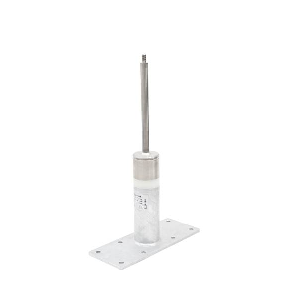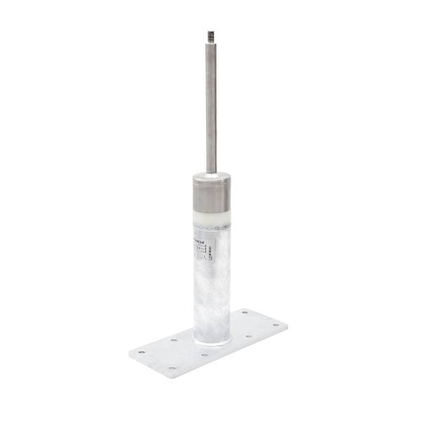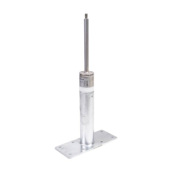
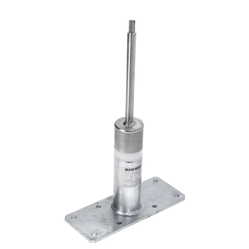
It is a linear anchoring system, that is, a line (flexible or rigid) between end and/or intermediate anchors, to which the operator is attached. The operator is required to wear Category III PPE (Personal Protective Equipment) to protect against falls, secured to the line either by a connector or a mobile anchor point.
The durability of a product is defined by the manufacturer, but depends on many factors including the quality of the materials used, their use, atmospheric agents, environmental conditions of the place where the lifeline is installed, etc.
Yes, a lifeline must be certified according to the reference technical standards: UNI EN 795:2012 (for removable devices types A and C), CEN/TS 16415:2013 (for removable devices types A and C) and UNI 11578:2015 (for permanent devices types A and C).
Whether a lifeline complies with one or more of the above standards depends on its intended use, and therefore it does not necessarily have to comply with all three standards at the same time.
It is the manufacturer's responsibility to issue a declaration attesting the product's compliance with the reference standard.
No. All lifelines composed of anchors compliant with the UNI 11578:2015 standards (for permanent type A and C devices), UNI EN 795:2012 (for removable type A and C devices) and CEN/TS 16415:2013 (for removable type A and C devices) are suitable for use with PPE against falls from a height.
The only certified connections between lifelines or type B webbing and PPE (Personal Protective Equipment) are connectors compliant with UNI EN 362.
The choice depends on the characteristics of the supporting structure. In the event of a fall, rigid poles generate significant forces, which are then transmitted to the anchors and the supporting structure; deformable poles, on the other hand, absorb more loads, transferring less to the anchors and supporting structure. Therefore, where the supporting structure is not suitable for withstanding high stresses, elastoplastic deformation poles are preferable.
The UNI EN 795:2012 standard does not specify any particular material, but recommends that the cable does not show any corrosion and that, in the case of galvanized wire ropes, the galvanization complies with ISO 2232.
The number depends on the standard according to which the lifeline is certified and must be indicated by the manufacturer in the user manual.
There are many possible fastening methods, each closely related to the type of structure on which the anchoring system is installed. They can be secured using a plate and counterplate, screws and nuts, or using rods and two-component resins, wood screws, mechanical anchors, rivets, clamps, etc. However, it remains the responsibility of the engineer in charge to verify the type of anchor and the structure and indicate its characteristics and dimensions.
Anchor points allow movement only in a circular area with a radius equal to the length of the lanyard, while lifelines allow linear movement along their entire length.
The choice of which fall protection system to adopt is the employer's responsibility, who selects the most suitable system based on the protective function it must fulfill (for example, installing a guardrail to protect against the risk of falling through the floor would be pointless). However, as indicated by Legislative Decree 81/2008, collective protection systems are preferable in the event of a risk of falling from an edge.
Connection to a lifeline by a rope access worker can be considered safe if the manufacturer has provided for this and reported it in the user manual issued by the manufacturer and if the operating conditions allow it.
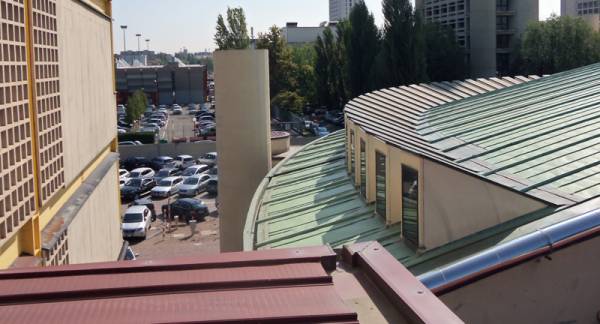
Roof renovation is an extraordinary maintenance project, meaning it doesn't fall under the scope of work that can be performed using a lifeline. It is, in fact, suitable for performing ordinary maintenance work, such as radio and television antenna repairs, Faraday cage maintenance, maintenance of roofing systems, re-roofing/replacing waterproofing membranes and sheaths, gutters cleaning, satellite dish repairs, solar panel or photovoltaic system installation or maintenance, etc.
Yes, subject to a risk assessment by a qualified technician and in compliance with current regulations regarding safety against falls from heights.
UNI 11560:2022 indicates that the documentation to be provided to the client must contain:
According to Appendix A2 of UNI EN 795:2012 – Guide for documentation to be provided after installation, the necessary documentation that must be provided to the customer must include:
This plan should be posted at the entry point to the building so that it is visible or available to everyone.
To answer the question, it is necessary to distinguish between load-bearing and non-load-bearing structures.
If the roof is practicable, it falls within the scope of fall protection systems and it is therefore necessary to proceed with a risk assessment to choose the most suitable protection system.
However, if the roof is not accessible or load-bearing, the installation of permanent devices is not possible, as access and transit are not foreseen.