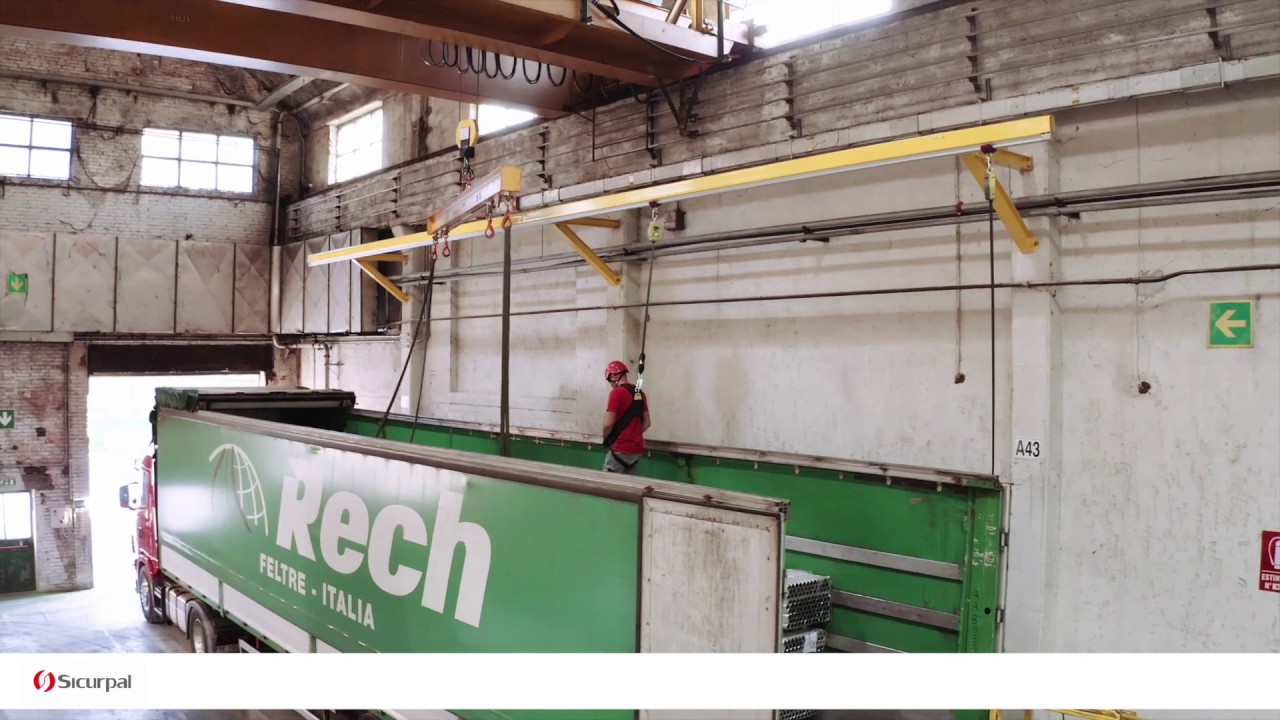
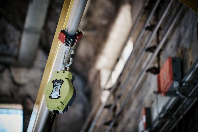

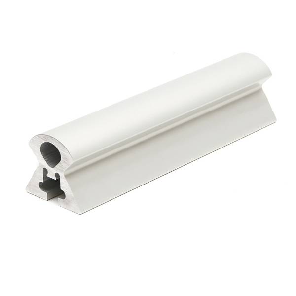
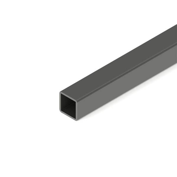
Alurail 3m long anodized aluminum fall arrest rail, can be fixed along the entire length of the profile. Ideal for ceiling-mounted lifelines where high smoothness is required.
Alurail 6m long anodized aluminum fall arrest rail, can be fixed along the entire length of the profile. Ideal for ceiling-mounted lifelines where high smoothness is required.
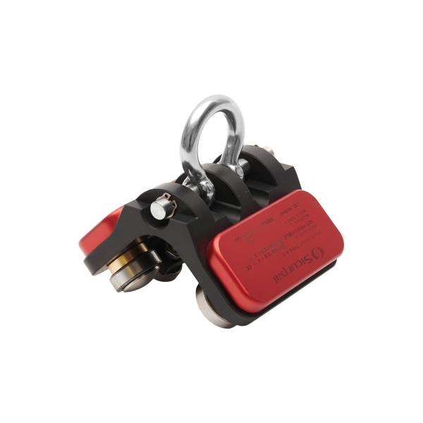
Trolley for Alurail L rail certified for the support of one person. Designed with high-strength anodised aluminium body and 316 stainless steel and brass rotating assembly. Anchor hook swivels 180° on perpendicular axis
CG: Alurail L tubular in accordance with customer's drawing
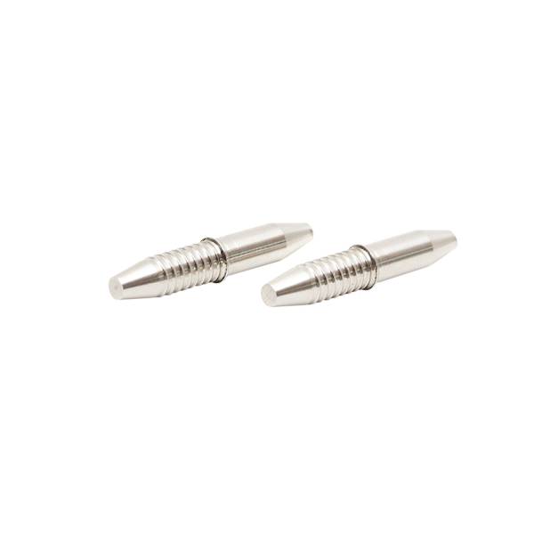
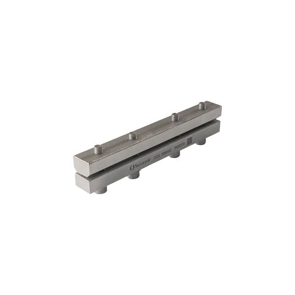
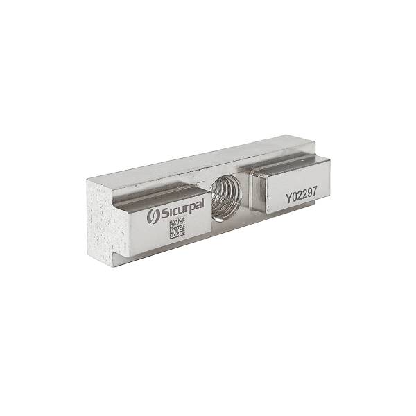
Junction for connecting Alurail L track, invisible model. Maximum connection span 1m
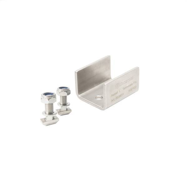
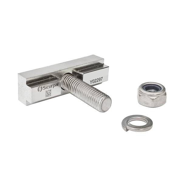
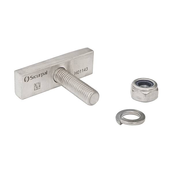
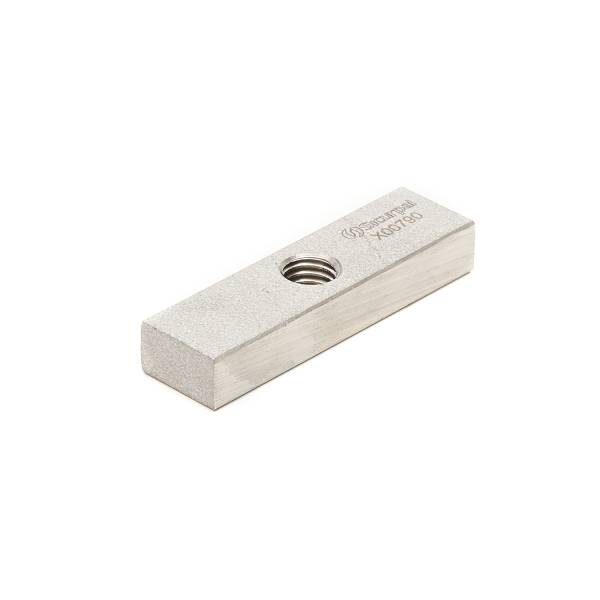
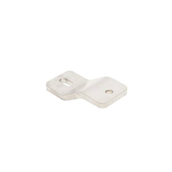
304L polished and marked fixing plate with 35 mm bar for Alurail L and S with grower washer and self-locking nut
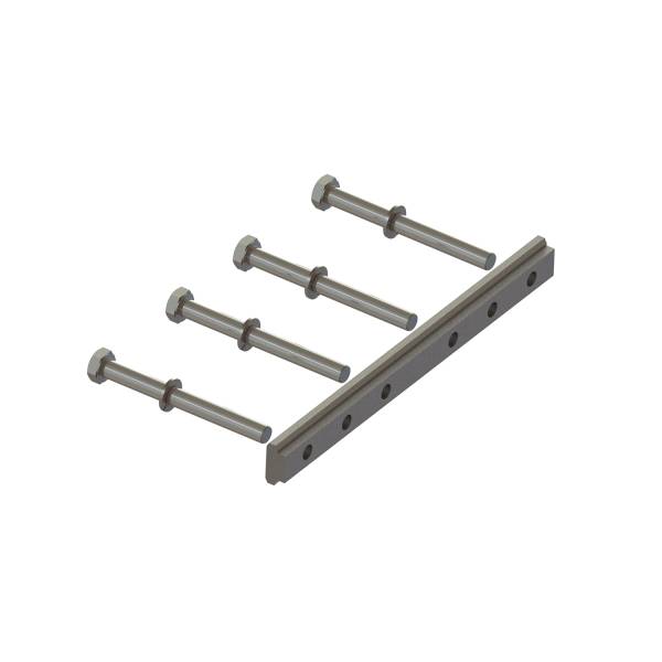
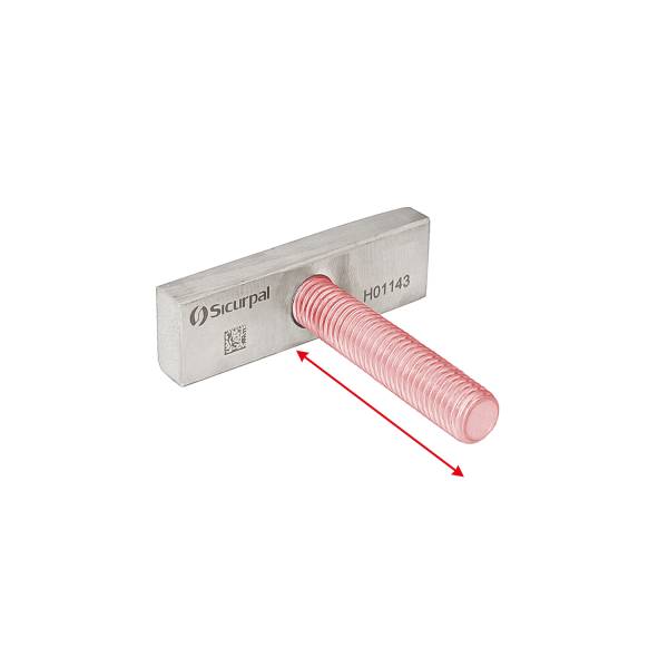
Generic Code: Fixing plate 304L electro-polished and marked with variable length bar customizable to drawing for Alurail L and S with grower washer and self-locking nut
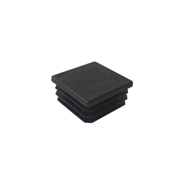
Alurail L plug for closing the outer profile of the rail. Optimal for wasp and water/ice protection.
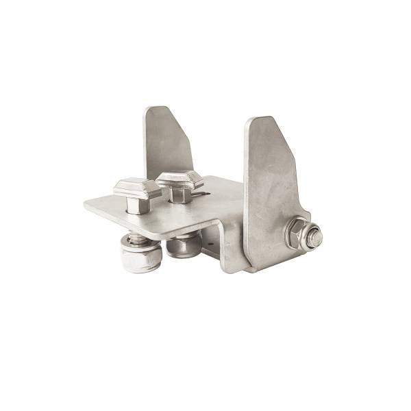
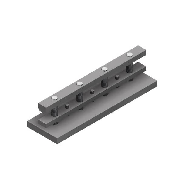
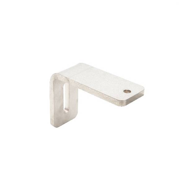
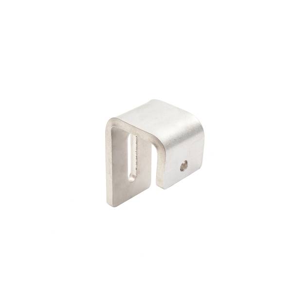
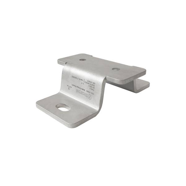
Hot-dip galvanized external plate with stainless steel fixing plates and bolts
According to UNI EN 795:2012 and Commission Implementing Decision (EU) 2015/2181 of 24 November 2015, only type B and E devices are required to bear the CE marking.
Maintenance, especially for safety systems, is mandatory (art. 15 DL 81/2008 and subsequent amendments). The Italian law regarding fall arrest systems requires an inspection according to the methods indicated by the manufacturer at least once a year or before their reuse if they have not been used for a long time (even several years).
The question is complex: what kind of testing are we talking about? The standard requires two tests: one regarding the anchors (the material used to attach them to the supporting structure: resin-threaded rods, structural screws, etc.), which must withstand the maximum forces generated by a falling operator, and a second to verify, in practice, that the installation has been carried out correctly. Unless otherwise specified by the manufacturer, for this last test, a force of 5 kN in the working direction must be applied to the anchor line post/plate for 15 seconds. In any case, both tests are mandatory; if the test is considered a test, the answer is YES.
The first action to take is to analyze the risks, and this cannot be done without taking into account the activities that will be performed.
All collective edge protection systems are included in the available solutions: parapets, safety nets, and combined systems (parapets and fall arrest nets). The choice of which to use depends on the characteristics of the roof and the client's needs.
Deformation-controlled devices dissipate part of the energy released during a worker's fall, thus reducing the load transmitted to the support structure. Although each device has its own breaking load, the elastoplastic deformation that the deformation-controlled device undergoes during a worker's fall must in no way lead to its failure.
Yes. In fact, UNI 11560:2022 requires that the interval between two periodic inspections (whether visual or instrumental) be no greater than 2 years for checks relating to the anchoring system and 4 years for checks relating to the supporting structure and anchors.
Yes. According to UNI 11560:2022, point 9.2.1, the system inspection after assembly must be performed by the installer and conducted in accordance with the instructions of the device manufacturer, the anchoring system designer, and the structural engineer. For anchors with the insertion of mechanical or chemical elements, the possibility of carrying out load tests that produce a tensile force of at least 5 kN for each anchor must be evaluated to verify the correct connection between the anchor and the supporting structure.
Yes. Since the purpose of an anchoring system is to connect the lifeline to a personal protective equipment (PPE) system to prevent falls from a height, a risk assessment must be performed prior to its design. This assessment involves analyzing the prevailing, concurrent, or subsequent risks and/or those associated with the work/activities to be performed on the roof.
It must necessarily be taken into consideration in order to design a system that protects the worker from such risks.
Pursuant to Article 59 of Legislative Decree No. 81/2008, liability lies with the worker if he or she fails to comply with safety obligations, observe personal protection provisions, use work equipment correctly, or participate in training programs.
In the event that the malfunction of one or more parts of an anchoring system is instead attributable to manufacturing or installation defects, the responsibility falls on the manufacturer and/or the installer.
UNI 11560:2022 indicates that the documentation to be provided to the client must contain:
According to Appendix A2 of UNI EN 795:2012 – Guide for documentation to be provided after installation, the necessary documentation that must be provided to the customer must include:
This plan should be posted at the entry point to the building so that it is visible or available to everyone.
Anchor points allow movement only in a circular area with a radius equal to the length of the lanyard, while lifelines allow linear movement along their entire length.
A rigid or track lifeline is an anchorage device that employs a rigid anchor line that deviates from the horizontal by no more than 15° (when measured between the end and intermediate anchors at any point along its length).
Main features:



.jpg)